 التبريد السائل مقابل التبريد الهوائي لأنظمة تخزين الطاقة: أداء عالي مقابل حلول منخفضة التكلفة
Apr 21, 2026
التبريد السائل مقابل التبريد الهوائي لأنظمة تخزين الطاقة: أداء عالي مقابل حلول منخفضة التكلفة
Apr 21, 2026
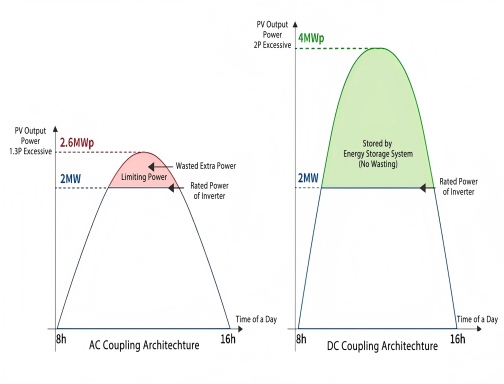 كيفية اختيار وصلة التيار المستمر ووصلة التيار المتردد في نظام تخزين الطاقة الشمسية؟
Feb 06, 2026
كيفية اختيار وصلة التيار المستمر ووصلة التيار المتردد في نظام تخزين الطاقة الشمسية؟
Feb 06, 2026
العلامات :
 الحماية من الجزر في أنظمة الطاقة الشمسية الكهروضوئية
May 12, 2025
الحماية من الجزر في أنظمة الطاقة الشمسية الكهروضوئية
May 12, 2025
 كيفية اختيار نظام الطاقة الشمسية الكهروضوئية المناسب: سكني مقابل تجاري
Jan 16, 2025
كيفية اختيار نظام الطاقة الشمسية الكهروضوئية المناسب: سكني مقابل تجاري
Jan 16, 2025
العلامات :
 حلول لمقاومة العزل المنخفضة ل "مقاومة العزل الكهروضوئية منخفضة جدا"
Jan 02, 2025
حلول لمقاومة العزل المنخفضة ل "مقاومة العزل الكهروضوئية منخفضة جدا"
Jan 02, 2025
العلامات :
العلامات :
العلامات :
هاتف : +86 -18655186412
بريد إلكتروني : Inquiry@sailsolarpv.com
Whatsapp : +86 -18655186412
Add : Building 7, Cross Border E-Commerce Supervision Zone, Hefei, China


© 2026 شركة سيل للطاقة الشمسية المحدودة كل الحقوق محفوظة
|خريطة الموقع |XML| سياسة الخصوصية